
Performance Hack #015 : Parts Assemblies Automation : Smart components
Overall Concept: Smart components
Smart Components and Smart Fasteners in SolidWorks 3D CAD software bring focused automation to the individual part level for designers and engineers, accelerating your design process, saving time and development costs, and increasing productivity.
Smart Components and Smart Fasteners Overview
SolidWorks Smart Components and Smart Fasteners have built-in intelligence that enables fasteners and various components to do some of the design work for you automatically. Store Smart Content in the CAD Library and then use it to speed your designs. Intelligent SolidWorks content items include:
1. Smart Components—Parts or assemblies that automatically create necessary clearance holes or cuts and assemble necessary associated components when added to a design (snap rings that cut their own mounting grooves, for example).
2. Smart Fasteners—Includes fasteners that automatically assemble and adjust length appropriately for part thickness, washers, and nut stack up.
3. Custom Content—Create your own Smart Content to meet specialized design needs.
When you make a component smart, you associate the other components and features with the Smart Component. When you insert the Smart Component into an assembly, you can choose whether or not to insert the associated components and features. The following features can be associated with a Smart Component:
o Extruded bosses and cuts
o Revolved bosses and cuts
o Simple holes
o Hole Wizard holes
Make Smart Component:
Most important to remember about smart component setup is that you need to do it one time for each Smart component desired, after that is it a ‘plug and play’ process. AKA this setup part is going to feel painful, but after that you will reap your rewards! This Smart component can then be used in any number of different assemblies.
Step-1: Create the Mock Assembly:
In this tutorial, we will learn how to create Receptacle part as smart components with a cut-out holes and hardware – two bolts and nuts as shown in below figure.

This part is modelled in SolidWorks using basic features.
1. Open the part: Receptacle part from smart component/receptacle.
2. Open the new part. Create simple rectangle part. 250mm x 100 mm. Create base flange Sheetmetal part. save part with plate name in similar folder.


3. Create base flange sheet metal part. Thickness 1.00 mm
4. Edit edge flanges- extrude 25 mm. Save part with Box name in your folder.


5. Open new assembly.
6. Insert Box part into new assembly.
7. Insert the Receptacle into assembly. Mate the part as per the below right image. (Any place on top surface somewhere in middle. We are not “fully define” part but because it is dummy assembly we are going to keep it simple without any specific dimensions for the purpose of this exercise).


8. Edit the mock assembly plate part in context. Right click on plate part and select Edit part.
9. Convert edges of cuts into sketch. Give dimension as per figure.

10. Apply Extrude cut through all.
11. Exit from edit assembly mode.

12. Add fasteners into assembly as below image from toolbox.
N.
Basically, here we created mock assembly for smart component, which is all that you need to make a Smart component with an associated Smart feature.

Step-2: Create the Smart component:
After you establish mock assembly: Make smart component
Assembly toolbar > Tools > Make smart Component.
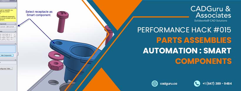
1. Select the Smart component:
Select component you want to make smart. From assembly please select the receptacle part.

2. Associate Components:
Select Components you want to associate with the Smart Component. You can select any associate part as components. As shown in figure select all fasteners as components.
")
3.Features:
Select Components containing features you want to associate with the Smart Component.
Select cut extrude as features.
 Note: You required in-context feature for Smart Component features.
3. Click ok. Smart Components are identified by in the FeatureManager design tree and in the graphics area.
Use the Smart Component:
Smart Components can be inserted into an assembly. You insert a Smart Component into an assembly and position it with mates, exactly as you do for any other component.
Step-1 Insert smart Component
1. Open assembly Box-2 from
smart component\receptacle
2. Open part Receptacle. Mate part as shown in figure.

Step-2 Insert smart Features.
3. Select Smart Component from feature tree and right click. Click on Insert smart features.

A preview window appears that highlights any reference faces needed to insert the associated components or features. Options selection is based on selection made at creating Smart Component.
4. Select the top face.
5. Select the Bottom face.


6. Select update feature and component size/location when smart component moves/changes.
Rebuild require updating each change.
7. The feature design tree lists Receptacle with all smart features and fasteners.

Modify the Smart Components:
Modify the Smart Component is easy. You can add, delete, or modify associated components, features, and mates of a Smart Component.
1. Open Smart component receptacle- smart component\receptacle
2. Select Smart Features in the Feature Manager Tree Folder and right click and select Edit in Defining Assembly.


3. Mock up Assembly Receptacle opens.

4. Right hand side you can see Edit Definition small toolbar.

5. Modify your assembly. You can edit new components or features. Save the assembly and click yes to save referenced Model.
6. New changes saved in the Smart Components data and Mock assembly disappears.
Exercise 1: Cupboard Hinge

1. Open assembly file Cupboard right end assembly. From Smart Component \ Cupboard folder
2. Add Smart fasteners: Select existing holes in hinge. Two pan slot screw should be added.

3. Create Smart Component: Make Cupboard Hinge as Smart Component. Tools > Make Smart Component. Select Cupboard Hinge Smart component.

4. Select fasteners as Components and hinge holes as features. Click ok and create the smart features.
5. Insert Smart Component Cupboard hinge in to the Cupboard right end assembly.
6. Mate Cupboard hinge as shown in below figure.

 - Insert Smart Features")
7. Insert fasteners and hinge holes. Practice inserting Cupboard hinge part into left sides.


Leave a Reply
Want to join the discussion?Feel free to contribute!