
Performance Hack #005 : Parts Assemblies Automation : Equations and linking Dimensions
Overall Concept:
In this tutorial, you will learn some of the advanced tools that are used to increase the productivity in the Part, of SolidWorks. These tools are used to create equations in part modeling. Equations are mathematical relations between the dimensions of a sketch or a feature. In an equation, the names of dimensions are used as variables.
Initial construction:
In this design you will need to see each dimension name so that you have the option to rename them. While individual dimension names can be hidden, it usually best to just rename those dimensions that you expect to appear in you design expressions. Dimension names are automatically created for every dimension you have produced, either at the sketch level, or through existing features. Most of the time these are not visible due to a setting we might have used to de-clutter our graphics area. Dimension names, when turned on can be viewed in the part and assembly files and can also be brought through to the drawing.
Most dimension names simply appear as, (D number) however they may vary dependent on a few settings on your system. Begin a new part and turn on dimension name display.
1. Please open the attached wood frame SolidWorks part file OR New> Part> Ok
2. Right click on Annotation folder> Show Feature Dimensions

3. Go to View> Hide and Show> Select Dimensions names.

May look something like this:

4. To actually re-name a dimension, either double-click on a sketch/or feature to bring up the available dimensions or “edit” said option. Now click in any dimension and re-name the feature in the property dialog box:

Once you have a set of dimensions possibly labelled and set to go, now we want to access the “Equations, Global Variables, and Dimensions” dialog box which can be accessed in a variety of ways. To add equations in a sketching environment or a part modeling environment, choose the Equations button from the Tools toolbar; the “Equations, Global Variables, and Dimensions” dialog box will be displayed.

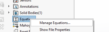
Alternatively, if you don’t see an equations folder in the tree, then you can manually turn it on via this short-cut:

Now, enable the Equations by setting the indicated option to “Automatic” or “Show”

Then, in the tree, right mouse click for “Manage Equations”:
The Equations, Global Variables, and Dimensions dialog box.
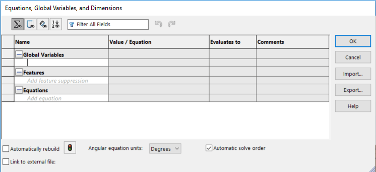
1. Equation View If the Equation View button is chosen in the Equations, Global Variables, and Dimensions dialog box, all global variables, equations for the features, and the dimensions applied to the active part will be displayed in the dialog box.
2. Sketch Equation View If the Sketch Equation View button is chosen in the Equations, Global Variables, and Dimensions dialog box, all global variables and equations applied to the active sketch will be displayed. Also, this button allows you to add, delete, or edit sketch equations.
3. Dimension View If the Dimension View button is chosen in the dialog box, all global variables, equations for the features, and dimensions of the part will be displayed in it. Note that, on choosing this button, all the dimensions of the active part will be displayed, even if the equations are not applied in it.
4. Ordered View If the Ordered View button is chosen, all equations and global variables are displayed in the order in which they are solved because the Automatic solve order check box is selected by default in the dialog box. To change this order, you need to clear the check box.
5. Rebuild the Rebuild button is used to refresh or update the sketches, models, or assemblies after editing the equations. If you have edited the equations in the Equations, Global Variables, and Dimensions dialog box, you will notice that the changes will not be affected automatically.
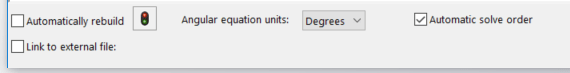
6. Automatically rebuild The Automatically rebuild check box is selected by default. As a result, the model gets rebuild automatically when you make any change in it. Be wary that this constant rebuild doesn’t impact processing times too drastically.
7. Angular equation units the options in the Angular equation units drop-down list are used to change the angular units to radians or degrees. By default, the Degrees option is selected in this drop-down list!
8. “Automatic solve order”: This check box is selected by default. As a result, SolidWorks automatically identifies the dependencies of the equations. As the equations in the Value / Equation column are dependent on the independent equations in the Name column, the equations in the Name column get solved automatically before the equations in the Value / Equation column. You may find this helpful if there’s been re-work of equations involved, or if the equations are failing to compute even with all the correct values and equations.
9. Filter All Fields the Filter All Fields search box is used to search the required equations, dimensions, features, and global variables in the dialog box.
10. Configuration: The Configuration drop-down list is only displayed when you are working over a part with multiple configurations and is used to display all the configurations. By using this drop-down list, you can select the required configuration and apply the equations and global variables to its dimensions. Make sure you hit “OK” and re-verify that correct equations hold per configuration and that you were careful in applying equations to specific configurations.
11. Link to external file The Link to external file check box is used to create link between an external text file containing equations and global variables and the active part. You can also export the applied equations and global variables of the active part to a text file by using this check box. Be careful in what you link to text files. Only part files can share the same text files, coupled with assemblies only being able to share the same text file. If you inadvertently link a part text file to an assembly environment you will get errors.
Adding Global Variables
In SolidWorks, you can add global variables by using the Equations, Global Variables, and Dimensions dialog box.
1. To do so, invoke the dialog box and choose the Equation View button, if it is not chosen by default. Next, click on the empty cell of the Global Variables node under the Name column and specify a name for the global variable in it.

2. click on the cell corresponding to this cell in the Value / Equation column; a shortcut menu will be displayed preceded by an equal to (=) sign. Also, the name specified for the global variable in the previous cell will be displayed in quotation marks.
3. Now, you can specify the value for the global variable by using the options available in the shortcut menu or by directly entering the desired value in the edit box. You can also select the dimensions from the drawing area as the value of the global variable.
4. You can perform various mathematical operations using symbols such as plus (+), minus (-) and so on, while specifying the values for the equation and global variable in the respective cell. You can also add a comment to the added global variable in its respective cell under the Comments column.
Global variable to link dimensions
1. You can also edit the equations from the drawing area. To do so, double-click on the dimension that has equations; the Modify dialog box will be displayed with the equations applied in it. Now, you can modify the equations as per your requirement.
2. Double click on a sketch dimension to bring up the Modify dialog box. By typing the equal sign you indicate to the system that you will start an equation.


3. After the equal sign you can start to type the name of the global variable. SOLIDWORKS does not recognize this as a global variable until you click the small “Create Global Variable” button that appears as you type
4. As soon as you click on the button, the global variable is created and allows you to edit its value.
5. To the left of the dimension is a toggle button that shows the global variable or the value.


6. To set another dimension to that same value, type the equal sign and then pick your new global variable and click the green check mark.
7. When you change the value of either of these dimensions, both dimensions are changed to the new value because you are really changing the value of the global variable.
Adding Equations:
1. You can also add equations to a sketch or a feature. To do so, create a sketch and apply dimensions to it. Next, choose Tools > Equations from the SolidWorks menus; the Equations, Global Variables, and Dimensions dialog box.
2. If you add equations in the Part mode, then you need to double-click on the feature or features whose dimensions are to be included in the equation. Next, select a dimension from the drawing area.
3. This dimension is called the driven dimension and it will have to equate with other dimensions. The other dimension that the driven dimension will equate with is known as driving dimension.
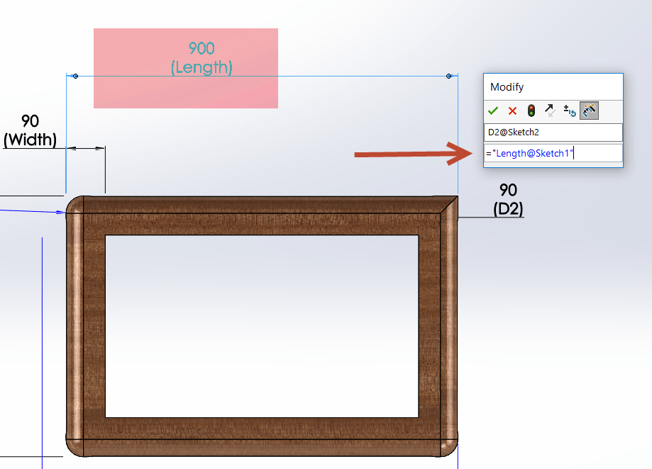
For Example: As shown in below image you would like to link some dimensions.
Step-1 Double click on the feature or dimensions.
Step-2 Apply equal sign.
Step-3 Now you can select any global variables to make equations or select preexisting sketch.


Step-4 Select sketch from graphics area. Now if you need you can add any mathematical relationship with sketch dimensions. For example: You can add here Length@sketch1 / 10.

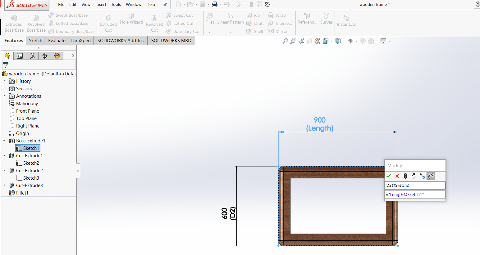
Step: 5 If you have too complex sketch and features. It can be difficult to recognize dimensions. You can select equations value from the feature manager tree. Please follow below steps to select it properly .
1. Double click on dimensions where you would like to apply equations.
2. Press = sign.


3. We need to expand hidden feature tree. Also expand features to select sketch. Once you select sketch you can see dimensions related to that sketch.

Replacing Equation References for Deleted Features
If you delete a feature that is referenced by equations, you might have errors in your equations. These errors occur when the equations for a deleted feature contain driving dimensions. You can repair the equations by replacing the dangling portion of the equations with other dimensions or variables in the Equations dialog box.
1. Do one of the following:
2. Click Equations ![]() (Tools toolbar).
(Tools toolbar).
3. Click Tools > Equations.
4. In the FeatureManager design tree, right-click Equations and click Manage Equations.
5. Select the Equation View ![]() .
.
6. Under the Value/Equation, in the dangling portion of the equation column, right-click Replace Reference.
7. In the Replace Dimension/Variable dialog box, type a global variable or dimension string to repair the dangling portion of the equation, or select it from the graphics area.
8. Now you can add any mathematical calculation to your equations.
Linked Values
Use linked values (also referred to as shared values or linked dimensions) to link two or more dimensions without using equations or relations. When dimensions are linked in this way, any member of the group can be used as a driving dimension. Changing any one of the linked values changes all others to which it is linked.
The variable name you specify becomes the name of the linked dimensions.
1. Select dimensions and right click. Select Link value from drop down list.
2. Provide name to link value. Click ok. You can see the link symbol in front of the dimension.


3. Now you can select the new dimensions and right click to link value. You can select link variable name from the drop down.


4. SolidWorks add link dimnesions as new global variables automatically into equations manager. Now when ever you change the value of one dimensios other linked dimension will change automatically. 


Leave a Reply
Want to join the discussion?Feel free to contribute!