Performance Hack #018 : Part Automation : Weldment Profile
OVERALL CONCEPT
When you first install SOLIDWORKS you get a small amount of weldment profiles in the “Default Database”. This can be a problem if you need additional sizes and shapes not currently offered in the existing databases. In this tutorial, we will discuss how to add more content whether from external databases or creating custom profiles.
FUNDAMENTAL SKILL: LOCATING WELDMENT PROFILES FOLDER
Know where you currently are reading Weldment Profiles from. Tools > Options > System Options tab > File Locations > Weldment Profiles drop-down menu.
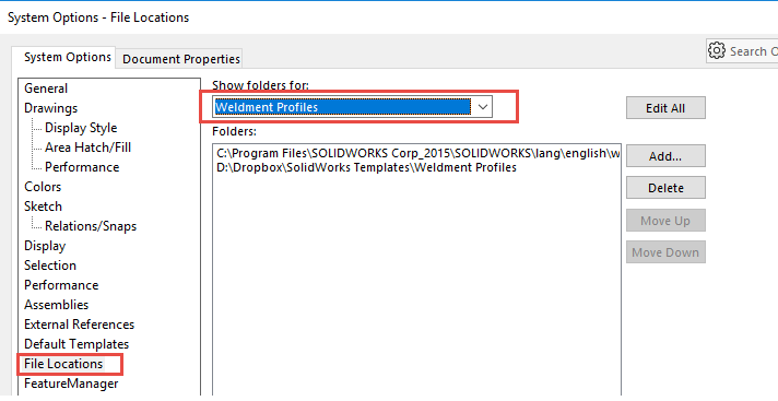
Now, as an additional side note, locations should always be unique and independent of the SolidWorks install.
If a location is listed as C:\Program Files\SOLIDWORKSCorp\SOLIDWORKS\lang\english\weldment profiles or very similar from the “Program Files” folder, this is the default install location. In some cases, with limited administration privileges you may find it difficult to write files to this “Program Files” folder. If you want to store your profiles in a separate location (recommended practice), you can create a separate folder structure, and then specify it as a weldment profile file location. This can be other locations on your hard drive, on different disk drives on your system, or on different computers on a network.
I have seen many cases where a client neglected to consider the final resting place of weldment profiles (whether customized or not); and with a clean removal of SolidWorks, lost ALL of his or her hard work. So please pay due diligence to the file location, downstream back-ups, share ability with other team members, etc.
R. A. Warren Structural Profile location:
PDM_Vault\RA_Vault\Library\Structural Steel
BACKGROUND INFO: DEFINING NON-CONFIGURABLE AND CONFIGURABLE PROFILES
From SOLIDWORKS 2014, an alternative, more efficient method of creating what is known as “configurable custom weldment profiles” has been made available.
Creating and using these configurable profiles is like using regular profiles, the main difference being file structure. Instead the file is saved as the style of the weldment i.e. “Round Tube” and configurations within that part dictate the various sizes, eliminating the need for so many files.
So you know, you can keep the old location of your existing weldment profiles present and run configurable profiles. Another benefit here, is that because each profile is based on one part, if you do decide to change your profile size, the position of the profile is remembered because you are using the same part (just a different configuration)
Other benefits of configured profiles:
• Due to the use of configurations to create various sizes, a design table can be used to create a vast amount of sizes very swiftly, saving large amounts of time by generating and manipulating multiple sizes simultaneously.
• Unlimited configurations can be created at once using this method. See the image below for an example of a design table.
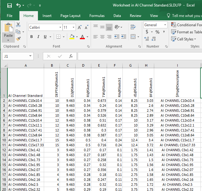
• Note that custom properties, sketch points and dimensions are carried through all configurations, so they only have to be set up once.
• Also, as of SolidWorks 2016, the size list is arranged alpha-numerically (smallest at the top), with an additional sub section at the top displaying the most commonly used profile for quicker selection. So, it is not important what order they are created in the design table.
DOWNLOAD DATABASES FROM “SOLIDWORKS CONTENT” CENTRAL
To boot, know that there is a small but limited selection of profiles when you enter the ‘structural feature’ after a fresh install of SolidWorks. (Image Left)
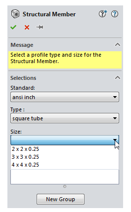
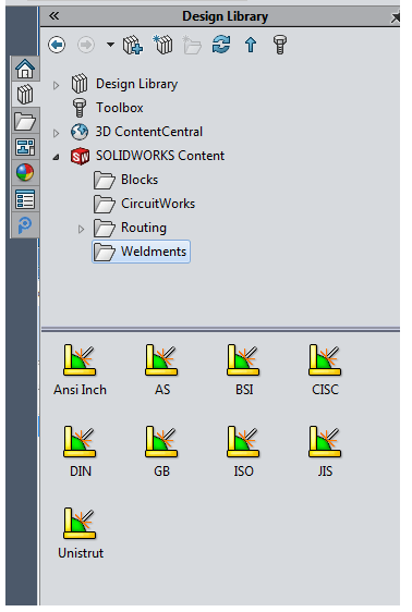
We can add more from the SOLIDWORKS Content in the Design Library inside SOLIDWORKS, right from the Task Pane (By default: is on the right-hand side of the SolidWorks window, the triple book icon).
1. Open SolidWorks.
2. Know where you currently are reading Weldment Profiles from. Re-visit section “Fundamental Skill: Locating Weldment Profiles folder” for further clarification.
3. Now we are ready for the fun part: open the Task Pane, and dig into the Weldments folder under the ‘SolidWorks Content’ section.
4. Use Ctrl + click to download a zip file for each standard that you want. When you Ctrl plus select the database, SolidWorks will then ask you where you want to save these files in a pop-up window. It is recommended to save the files to the same location listed in step 2.
5. Now, manually browse to this saved location in Windows Explorer.
6. Unzip the file to the same folder as your default weldment profiles (Step 2).
7. Start a new ‘test’ part, start a sketch, drop a line, start the structural member feature, and test that you can see these new profiles.
DOWNLOAD SOLIDWORKS CONFIGURED WELDMENT PROFILES
1. Obtain a copy of “Configured-Weldment-Profiles.zip” file set. These configured profiles don’t seem to be available through the additional SolidWorks content just yet, but are available for you to use.
2. Copy the contents of the ‘Weldment Profiles’ folder to your weldment folder location. These particular profile folders have been suffixed with “Configurations” so they should be easy to spot.
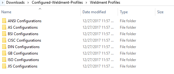
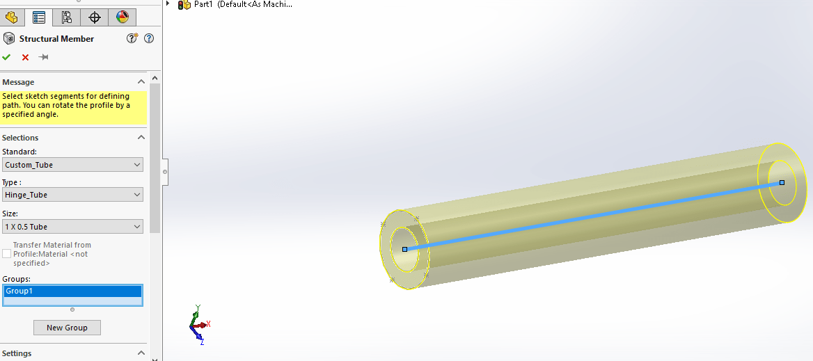
3. To give you an overview of how the system picks these up, the standards box reads the folder name, the type box will pick up the file, and the size box will now read the configuration data from within the file.
HOW TO CREATE CUSTOMIZED WELDMENT PROFILES
Now, if what you are wanting is not in the realm of normal structural members we can always add a custom profile. The same would be true if you need a standard shape, but the size you want does not currently exist.
The custom profiles can be handy for industries like Windows, Doors and Cabinets manufacturers where unique and customized profiles are the norm.
The overall concept is that we will open a new part, and create a sketch of the profile that we need. Specific points of concern are discussed below, along with setting up more powerful ‘configured sketches’. Configured profiles are great, because we can set up a single sketch, but then tweak the options to give us an ‘array’ of sizes that we need.
1. The first thing you need to do is to draw a sketch that will represent your overall profile shape.
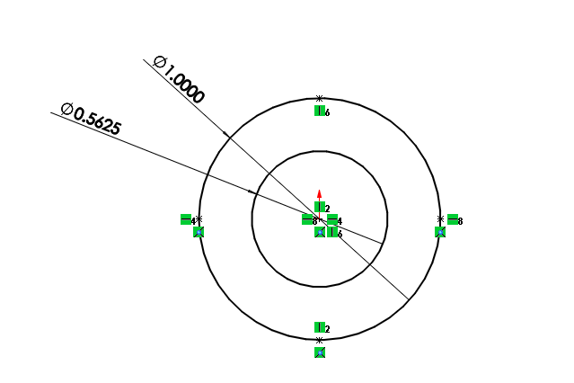
2. Draw your profile, taking into consideration design intent and any sketch ‘points’ you may want to use later on in the structural feature to locate the profile. Make sure to properly position your sketch around the origin.
3. Name any dimensions you want configured in your profile, or that could be labelled for easier identification. You can do this by clicking on a dimension and renaming it in the “Primary Value” box of the dimension properties box.
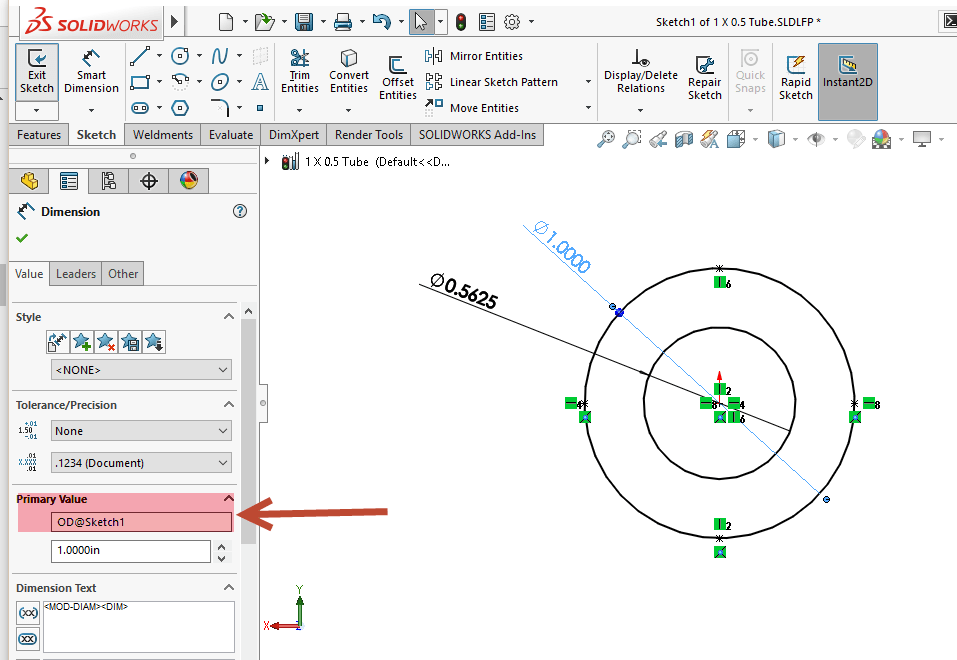
4. In this example, the 1.0“ dimension has been renamed to “OD” and the 0.5” dimension has been renamed to “ID”.
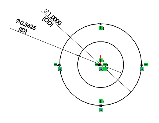
• Note: To show your feature dimension names right inside the sketch: Click View > Hide/Show > Dimension Names or Hide/Show Items > View Dimension Names (Heads-up View toolbar).
 OR
OR
5. Locate and Confirm your ‘working’ weldments profiles folder.
6. Ensure that you have exited the sketch. You should not be in “edit sketch mode”. This is critical to saving the profile correctly.
7. In order to save this profile correctly, we FIRST need to select the sketch in the tree, and THEN do “Save As”.
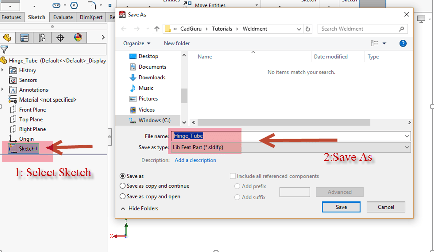
8. In this pop-up window, ensure that you are first writing to the correct weldment profile location, then write your file name in. A common practice is to name the file using profile dimensions. Under the Save as type, be sure to select “Lib Feat Part”. If this step is done correctly, after saving, a small green “L” will appear over the Sketch Icon in the Feature Tree to indicate that it is a Library feature.
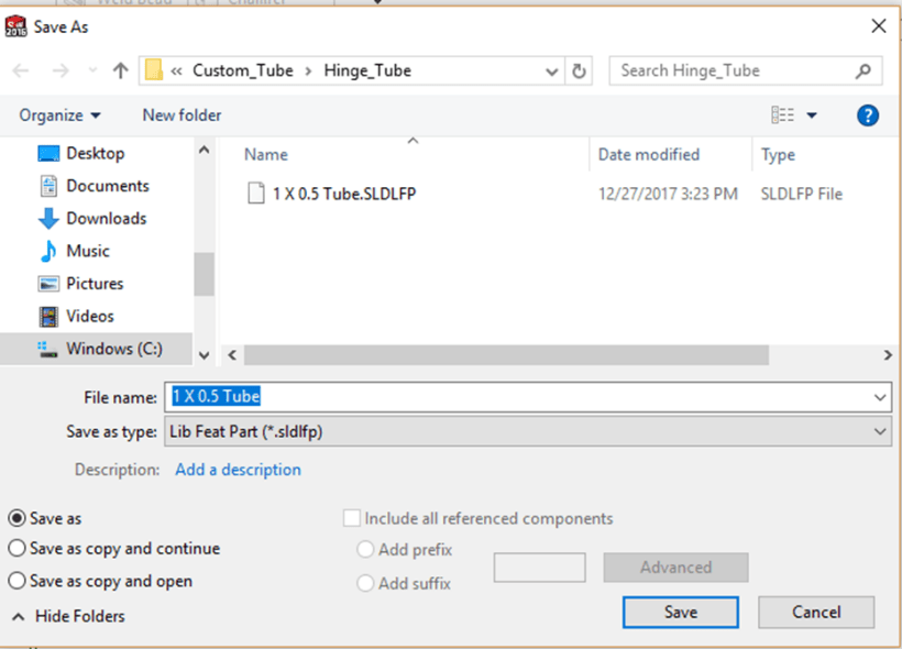
Additionally, if you are creating custom weldment profiles for the very first time, and are also setting up a customized folder location know that the final folder destination is very important. For non-configured profiles, the actual Lib Feat Part should reside 2 folder levels deep. The first folder sets the “standard”, the second 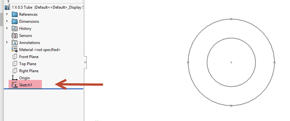 folder sets the “Type”, and the Lib Feat Part will then show up as the “size”
ADVANCE STEPS IF YOU NEED TO CONFIGURE YOUR PROFILE SKETCH
1. Click “File” and select “Properties”. Navigate to the “Configuration Specific” tab. Add a Property Name “Description” and a value describing your profile. In this example, “1 x 0.5 Tube”.
2. Add any additional properties you may want. These properties can be used in weldment cut lists, other tables and notes.
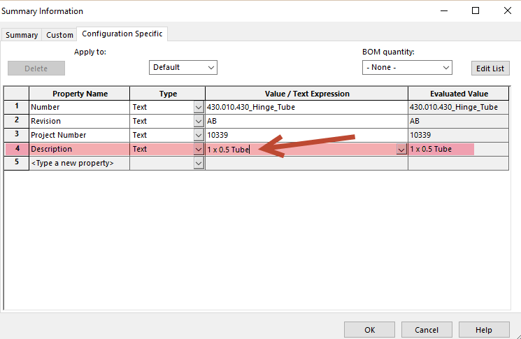
3. Right click on your sketch and select “Configure Feature.”
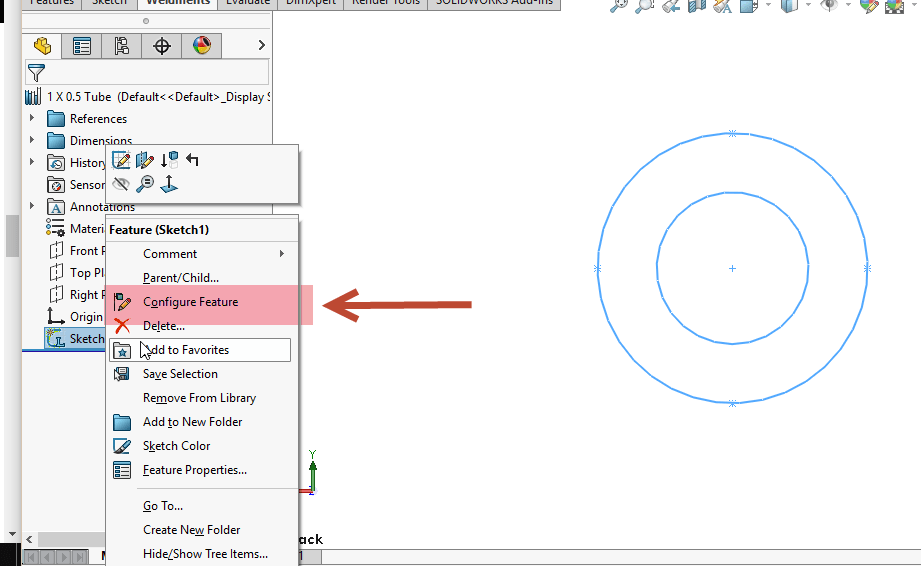
4. This brings up the Modify Configurations Table. Click the dropdown arrow next to “Sketch” and check the dimensions you want to configure. Notice that this example uses the OD and ID dimensions named earlier in this Tutorial.
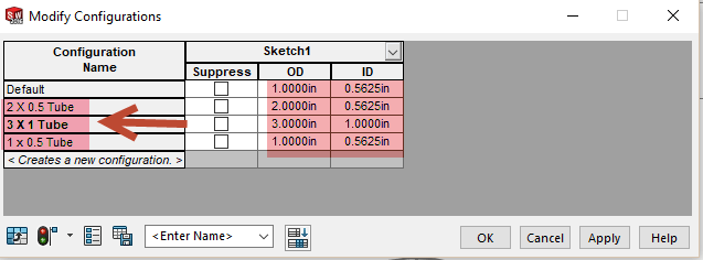
5. Now is a good time to save this table view. Enter a name in the text box in the bottom left. In this example, I entered “Sketch Config.”
6. Then, click “Save Table View”. This will allow you to recall this table if you need to use it again by clicking the dropdown arrow next to where you entered the name of the table view.
7. Right click on the Default Configuration and choose “Rename Configuration”. It is suggested to use the Dimensions.
8. Create any new configurations by clicking “Create a New Configuration” and naming it.
9. Modify the dimensions and descriptions in the table to match the configurations. Click “Apply” and “OK” when finished.
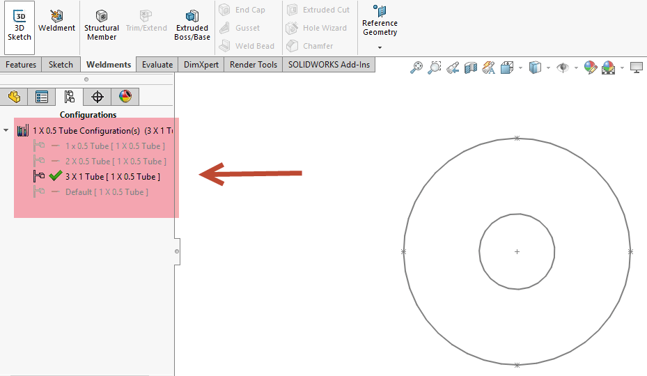
10. Cycle through your configurations to check their behavior.
11. Test your new profile in weldments!
WELDMENT PROFILE NOT SHOWING UP? TROUBLESHOOTING TIPS AND TRICKS
If you are not able to still see profiles when using the structural feature, please consider the following:
1. Path: Check Weldment profile path once again. Make sure path is added to SolidWorks weldment profiles. If you find paths disappearing after a re-boot, this is indicative of insufficient OS registry rights for the SolidWorks folder.
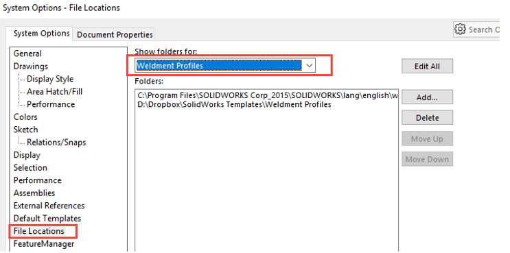
2. Admin Rights: Please confirm that you have ‘read and write’ rights for the weldment profile folder location. If you are experiencing issues with saving your file: save it on your local disk (Example: Desktop). Then copy files to the main weldment profile folder.
3. Re-Open SolidWorks: Occasionally it is needed to close and re-open SolidWorks before new profiles show up.
4. Sketch save as library: If you received an error message “Library Feature is empty.” when creating a structural member using a custom weldment profile: this means that the profile sketch has not been properly added to the library. Check the following:
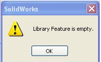
• Please re-open your model sketch and ensure that you have exited “edit sketch mode”. Then follow the steps outlined in the section “How to create Customized Weldment Profiles” and re-save as a .sldlfp file type.
• In the .SLDLFP file, right-click the profile sketch in the FeatureManager tree, then click “Add to Library”. In the resulting .SLDLFP file, if steps are done correctly, there should be an “L” over the sketch icon in the FeatureManager tree.



Leave a Reply
Want to join the discussion?Feel free to contribute!