Performance Hack #017 : Drawings Automation : Importing Dimensions and Tolerances from Part to Drawing
OVERALL CONCEPT
You might have gone through the tiring process of adding dimensions with tolerances at Part level and again in Drawing View. It can be time consuming and laborious. In this tutorial we are going to learn how to import those dimensions automatically from Part.
STEP-1 ADD DIMENSION WITH TOLERANCE INTO PART
1. Open the attached sample part file. (Tol_test.prt. – Please attached part link here)
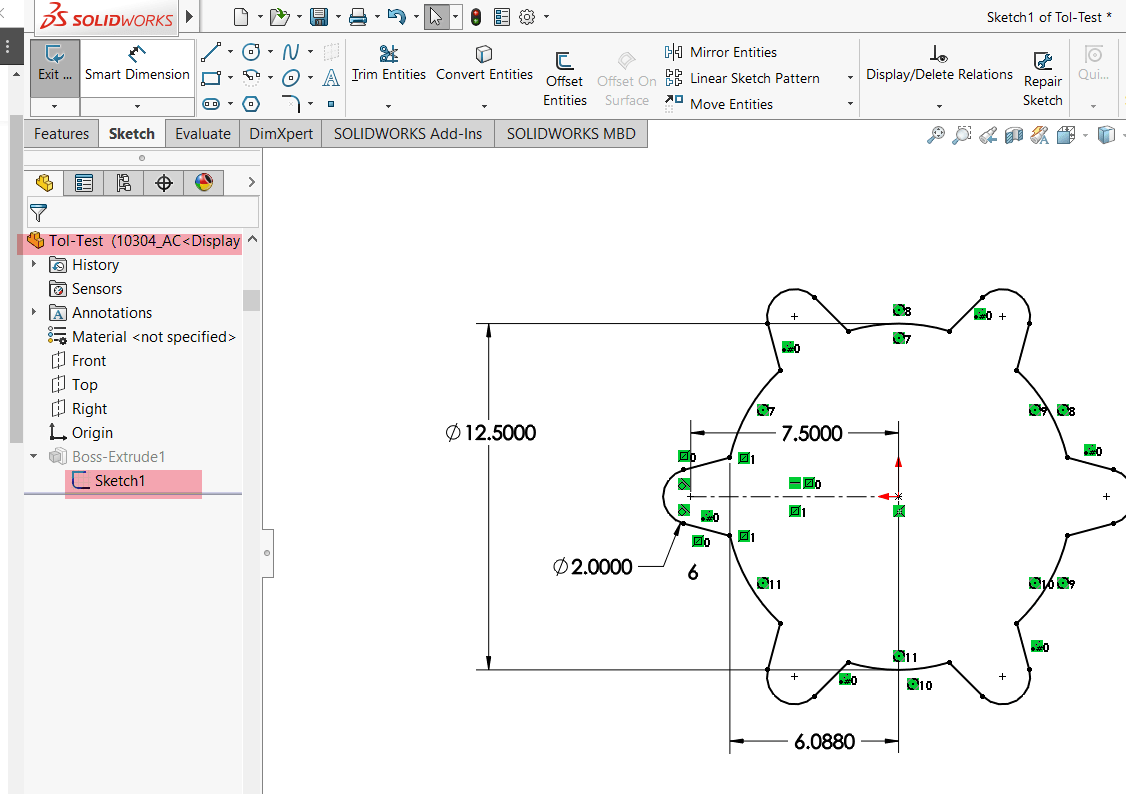
2. To add required tolerances into dimensions please Select Dimension and tolerance details into dimension properties manager.
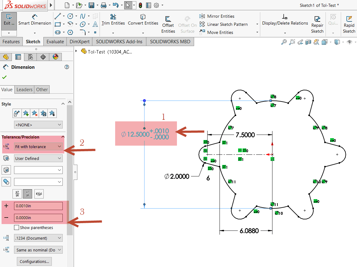
EXAMPLES OF DIMENSION TOLERANCE AND PRECISION
You can set tolerance and precision options in the Dimension Value Property Manager, as shown in these examples. If the part has multiple configurations, click Configurations to change selected configurations. Changes to tolerances of driving dimensions in the drawing are propagated to the model.
Select one of the following from the list: None, Basic, Bilateral, Limit, Symmetric, MIN, MAX, Fit, Fit with tolerance, or Fit (tolerance only). You can set Tolerance type to None and then set the variations and font to defaults for the current document. When you modify the properties of a dimension, the default tolerance settings will be those set in these options.
1. Basic: Adds a box around the dimension text. In geometric dimensioning and tolerancing, Basic indicates the theoretically exact value of the dimension.
2. Bilateral: Displays the nominal dimension followed by separate upper and lower tolerances. In and, set values for the amounts over and under the nominal.
3. Limit: Displays the upper and lower limits of the dimension. In and, set values for the amounts over and under the nominal. The tolerance values are added to and subtracted from the nominal.
4. Symmetric: Displays the nominal dimension followed by the tolerance. In, set the same value for the amounts over and under the nominal.
5. MIN: Displays the nominal value with the suffix MIN.
6. MAX: Displays the nominal value with the suffix MAX.
7. Fit tolerances: Sets the tolerance by Classification and alphanumeric values.
Tolerance values:
Specify the Maximum Variation and/or Minimum Variation values as appropriate for the type of tolerance that you selected.
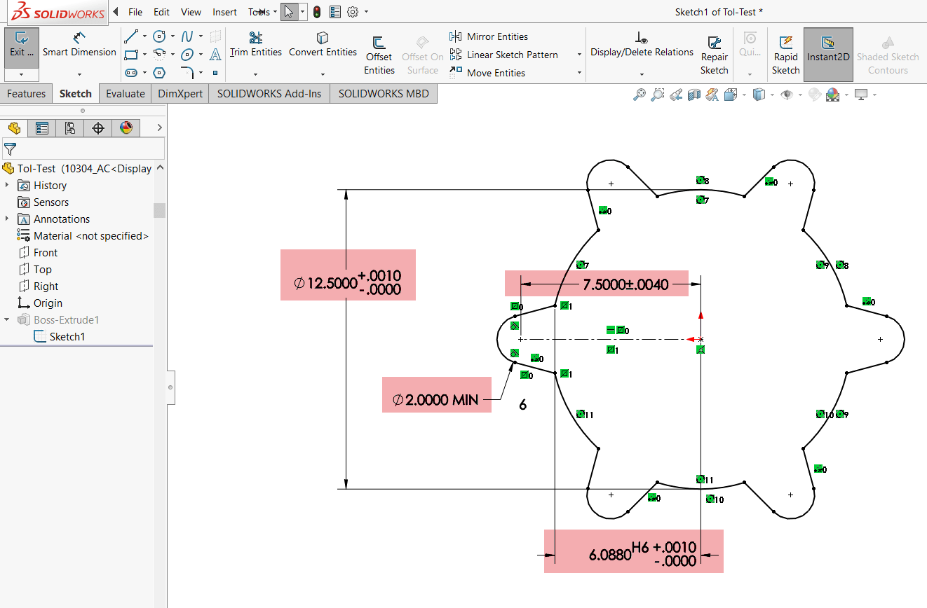
STEP-2 AUTO POPULATE DIMENSIONS INTO DRAWING VIEWS:
Now let’s see how we can save our time.
1. Make Drawing from the part.
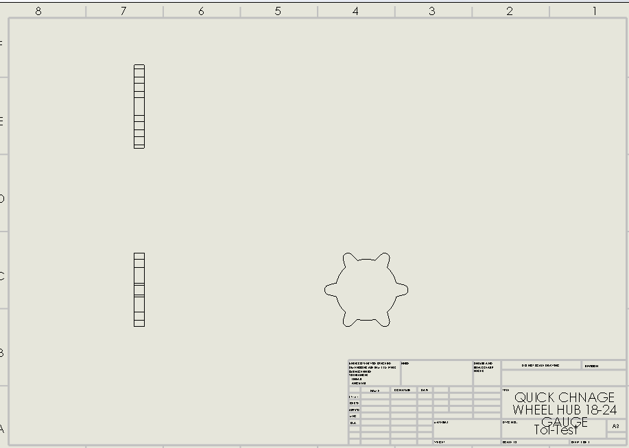
2. Insert 3 standard view into Drawing file.
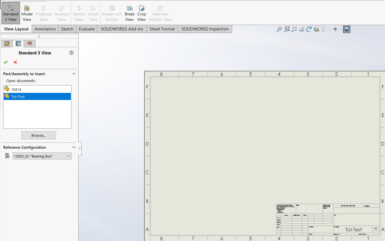
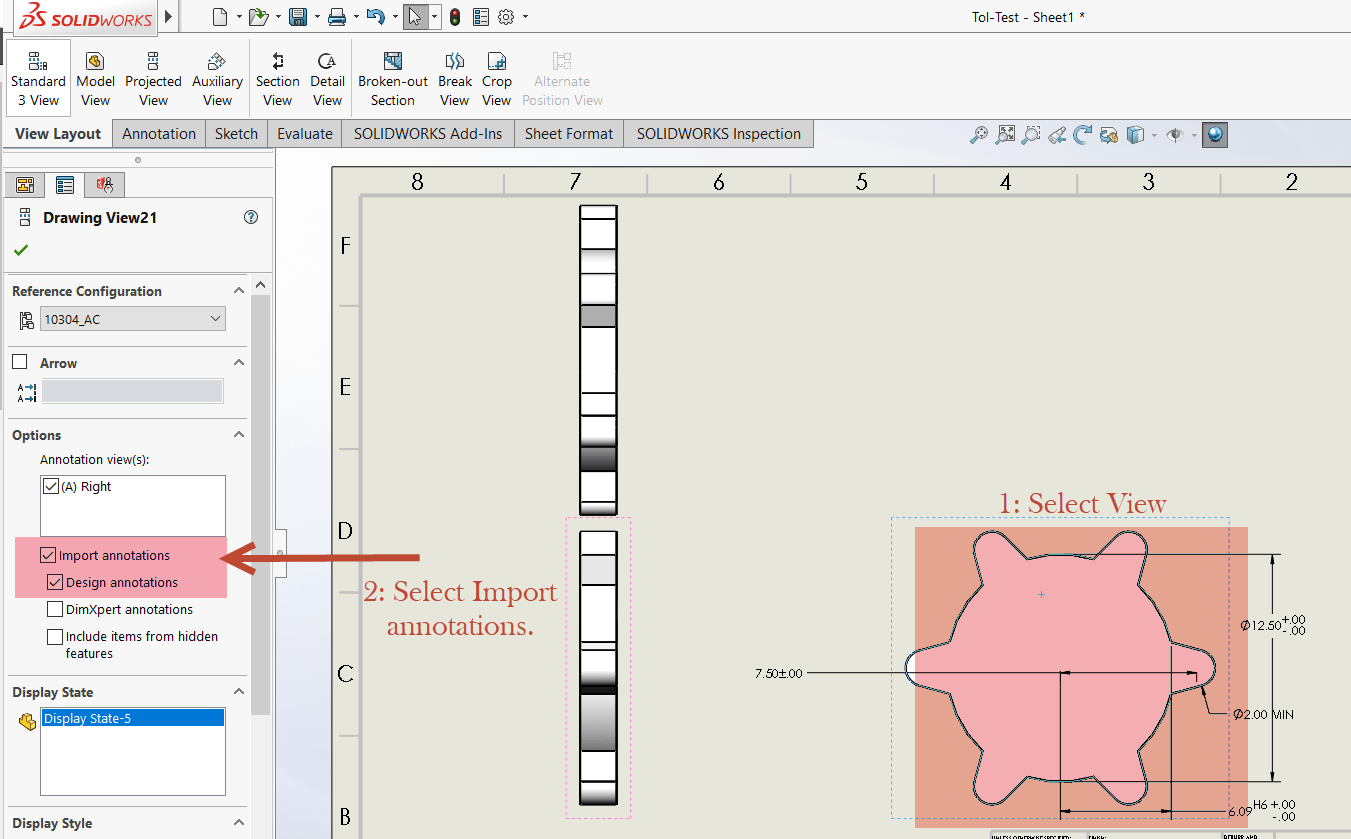
3. Now we are going to select view where we would like to add dimensions. Make sure you click the check box next to import annotations and design annotations. If you need to add dimensions in multiple views, please feel free to repeat this process. Unfotunately this setting cannot be found when you ctrl or shift select multiple views at once. Must be done independently per view.
STEP-3 MODEL ITEM DIMENSIONS WITH TOLERANCES:
SOLIDWORKS has just the right tool for you! It’s the SOLIDWORKS Model Items tool, and it’ll speed up dimensioning time in your drawings and make annotations a breeze. Model Items can be used for inserting items into an assembly component, an assembly feature, a drawing view/views, and a selected feature.
1. Below you’ll see a drawing with the three standard orthographic drawing views. This includes the front, top, and right profile views of the model. The Model Items tool can be found within the Annotations tab in the CommandManager.
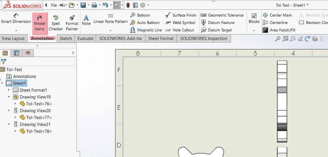
2. With the Model Items tool selected, the Property Manager will appear with several different options that we will run through, to bring in the driving dimensions, annotations, and reference geometry the way that we’d like.
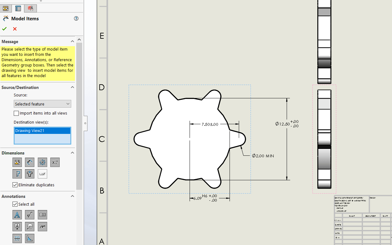
a. Choose the entire model as the source, so that all the dimensions and annotations from the model will be imported, rather than just dimensions and annotations from a single feature.
b. We have ability to choose the types of dimensions that will be imported from our model. There are seven different dimension options to choose from, which are as listed:
Dimensions that are marked for drawing
Dimensions that are not marked for drawing
Instance/revolution counts
Tolerance dimensions
Hole wizard profiles
Hole wizard location
Hole callout information
STEP-4 AUTO ARRANGE DIMENSIONS:
Now let’s do some clean up by using the built-in Auto Arrange Dimensions tool. To use this function, select all of the dimensions in a view and hover over the icon that appears when doing so.
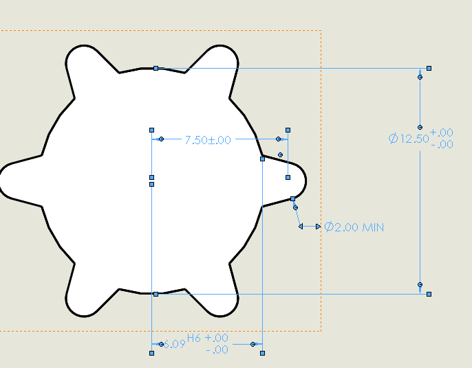
1. Once the dimensions are selected make sure you do not move your mouse too far. There is an icon not too far from your cursor.
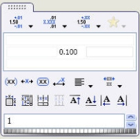
2. Select above icon it will expand into a mini toolbar.
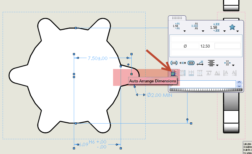
3. Please select the Auto Arrange Dimensions icon. Now magic all your dimensions nicely into positions that make sense.
I hope you find this tutorial helpful. If we have 10 views and hundreds of dimensions How much time would we have saved here. No need to repeat dimensions or tolerance or waste time to re-arrange it.



Leave a Reply
Want to join the discussion?Feel free to contribute!